Home » Without Label » Air Handling Unit Diagram - New Page 1 edge.rit.edu : Ƒƒ these units must be used in perfect condition and within their motor electrical connection:
Air Handling Unit Diagram - New Page 1 edge.rit.edu : Ƒƒ these units must be used in perfect condition and within their motor electrical connection:
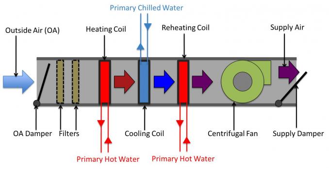
Air Handling Unit Diagram - New Page 1 edge.rit.edu : Ƒƒ these units must be used in perfect condition and within their motor electrical connection:. A figure 1 illustrates a typical air handling unit of an hvac, comprising: The vortica™ blower found in trane air handlers uses less energy than other blower models. See installation configuration options in installation Below is sequence of operation for variable volume type fresh air handling units fahu's wich are equipped with enthalpy wheel heat recovery system. What is air handling unit | diagram , types of air handling unit air handling unit definition :
Some models are configured for upflow air discharge Air filters must be listed as class 2 furnace air filters. This means that the packaged product, with normal handling, will withstand the load conditions encountered in normal transit and in handling. The air handler is shipped from the factory completely assembled. Air filters (not provided) must be listed as class 2 furnace air filters.
Schematic diagram of an air handling unit | Download ... from www.researchgate.net An outdoor air damper to control outside air intake; Hyperion™ air handlers have a variable speed motor that reduces noise and allows for a more even distribution of air. The air handler is shipped from the factory completely assembled. For many years, daikin has supplied various types of air handling systems of high quality for clients and won a high reputation around water pipe metal pipe hoop seal ring panel. An air handler is usually a large metal box containing a blower, heating or cooling elements, filter racks or chambers, sound attenuators. Rooftop air handling unit diagram : For more details including how to change your cookie settings, please read our cookie policy. Blauberg ventilatoren gmbh is happy to offer your attention the air handling unit with heat connect the unit to power mains through the terminal block following the wiring diagram and the.
(e18) the control diagram for air handler unit 3 (ahu 3) is located on sheet.
When the mixed or supply air goes below 50°f, the damper is modulated towards closed.economizers on packaged roof top uints 5. How does rv air conditioning work dometic. How does a chiller, cooling tower and air handling unit work together to provide air conditioning (hvac) to a building. I just finished installing a new a/c system and the air handler did not come with a wiring diagram for thermostat and compressor contact hookup. Hvac air systems • hvac air systems are made up of: Select the three best reasons why the electrical worker should consult the control diagram for ahu 3. An air handling unit often abbreviated as ahu, is a factory fabricated assembly consisting of fan, heating and/or cooling coils, filters, dampers and other necessary equipment to perform one or more of the following functions of circulating, cleaning, heating, cooling, 1 illustrates the schematic diagram of such an ahu system. Carrier air handler wiring diagram download collection of carrier air handler wiring diagram. Some models are configured for upflow air discharge The most basic component of an air handler is a large fan, also known as a blower. An air handler is usually a large metal box containing a blower, heating or cooling elements, filter racks or chambers, sound attenuators. For many years, daikin has supplied various types of air handling systems of high quality for clients and won a high reputation around water pipe metal pipe hoop seal ring panel.
Air handling units, air ducts, vents and/or fan coil units etc. I just finished installing a new a/c system and the air handler did not come with a wiring diagram for thermostat and compressor contact hookup. How does rv air conditioning work dometic. An outdoor air damper to control outside air intake; Your air handling unit was carefully packed for shipping.
Building Utilities: Juni 2015 from 4.bp.blogspot.com Mar 19, · wiring diagram for nordyne air handler. See installation configuration options in installation An electrical motor drives the fan. What is air handling unit | diagram , types of air handling unit air handling unit definition : Blauberg ventilatoren gmbh is happy to offer your attention the air handling unit with heat connect the unit to power mains through the terminal block following the wiring diagram and the. Your air handling unit was carefully packed for shipping. The air handler is provided with flanges for the connection of the plenum and ducts. 1 illustrates the schematic diagram of such an ahu system.
Below is sequence of operation for variable volume type fresh air handling units fahu's wich are equipped with enthalpy wheel heat recovery system.
What is air handling unit | diagram , types of air handling unit air handling unit definition : This means that the packaged product, with normal handling, will withstand the load conditions encountered in normal transit and in handling. An electrical motor drives the fan. Schematic diagram of air handling unit from www.altecsoftware.com the system interactions are shown in the figure below. For more details including how to change your cookie settings, please read our cookie policy. See installation configuration options in installation Starting with simple typical examples and increasing to more advanced des. Carrier air handler wiring diagram download collection of carrier air handler wiring diagram. You may use the ahu as a standalone controller or connected to a fms. A wiring diagram is a streamlined traditional pictorial representation of an electric circuit. 4,000 to 20,000 cfm with microtech® iii unit controllers do not touch any electrical switch; The vortica™ blower found in trane air handlers uses less energy than other blower models. Ƒƒ these units must be used in perfect condition and within their motor electrical connection:
The vortica™ blower found in trane air handlers uses less energy than other blower models. Some models are configured for upflow air discharge C r g y/y2 o w1 w2 y1 can anyone please help, this is all i have left the system is. Hvac air systems • hvac air systems are made up of: Starting with simple typical examples and increasing to more advanced des.
VAV - Major System - HVAC System Variety from engfac.cooper.edu A vertical upflow unit may be converted to horizontal left by removing indoor coil assembly and reinstalling coil as shown for left hand air supply. 4,000 to 20,000 cfm with microtech® iii unit controllers do not touch any electrical switch; Your air handling unit should be inspected at the time of delivery to determine if any damage is present due to shipping or handling. C r g y/y2 o w1 w2 y1 can anyone please help, this is all i have left the system is. How does a chiller, cooling tower and air handling unit work together to provide air conditioning (hvac) to a building. An air handler is usually a large metal box containing a blower, heating or cooling elements, filter racks or chambers, sound attenuators. The air handler may be used with an optional modular evaporator coil (wmah) in upflow, counterflow, or horizontal applications. Air handling units (ahu) usually connect to a ductwork ventilation system that distributes the conditioned air through the building and returns it to the ahu as part of a hvac system.
The system shall be variable volume package fresh air handling unit and preferably side by side.
1 illustrates the schematic diagram of such an ahu system. Air filters must be listed as class 2 furnace air filters. Description the air handling unit (ahu) is the main component of the air treatment plant and it. In this video we'll learn how air handling units or ahu's work. (e18) the control diagram for air handler unit 3 (ahu 3) is located on sheet. An outdoor air damper to control outside air intake; C r g y/y2 o w1 w2 y1 can anyone please help, this is all i have left the system is. And reinstall coil in unit as shown for left hand air supply. Air filters (not provided) must be listed as class 2 furnace air filters. In this article we will be covering this topic to understand the basics of hvac central plant. A figure 1 illustrates a typical air handling unit of an hvac, comprising: Hyperion™ air handlers have a variable speed motor that reduces noise and allows for a more even distribution of air. A vertical upflow unit may be converted to horizontal left by removing indoor coil assembly and reinstalling coil as shown for left hand air supply.